Get P Controller Circuit Diagram Pictures. 15 ampere charge controller circuit diagram used analog electronics components to control the flow of charges from solar panel to battery. Integral controller basics, block diagram & advantages in control engineering by engineering funda.
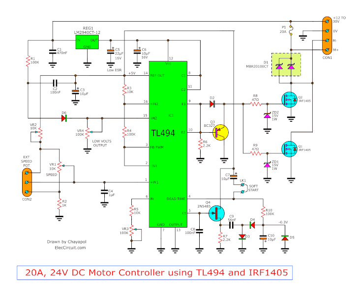
12V-24V PWM Motor controller circuit using TL494-IRF1405 from www.eleccircuit.com If the fan won't start at 25°c then temporarily. The maximum power point tracker (mppt) circuit is based around a synchronous buck converter circuit.it steps the higher solar panel voltage down to the charging voltage of the battery. Dc servo motor control system.
Specification of this popular inverter ac mains low/high voltage protection overload protection low battery protection capacity to soft start of bird sound generator circuit using arduino this is the schematic diagram of the birds sound generator.
A detailed block diagram of the system is shown in figure: It is an automatic power off circuit diagram. Rgb led light wall washer circuit diagram. Water flow valve timer controller circuit | homemade circuit projects.

0 Response to "P Controller Circuit Diagram"
Post a Comment